|
Cilindros
Redondos Del Aire Del Acero De aluminio Y Inoxidable
Cuadro del tecleo para conseguir dimensiones y especificaciones |
|
No. de la Parte
|
|
Cuadro Del Cilindro |
Tamaño Del Alesaje
(milímetro) |
Longitud Del
Movimiento
(milímetro) |
Opciones Del Montaje |
Features |
Standard |
Options |
|
MAL |
Cilindro |
 |
16
20
25
32
40 |
Max. 500mm |
Montaje Inferior, Montaje Delantero,
Montaje Posterior,
Universal, Hilo de rosca |
El Actuar Doble,
El Solo Actuar, Revés Que actúa,
Eje Doble |
Sello Del Buna-N-N, Tope |
Pistón Magnético,
EPDM,
Sellos De Viton |
|
MA |
Cilindro Del Acero Inoxidable |
 |
16
20
25
32
40 |
Max. 500mm |
Montaje Inferior, Montaje Delantero,
Montaje Posterior,
Universal, Hilo de rosca |
El Actuar Doble,
El Solo Actuar, El Actuar Reverso
Eje Doble |
Sello Del Buna-N-N, Tope |
Pistón Magnético,
EPDM,
Sellos De Viton |
|
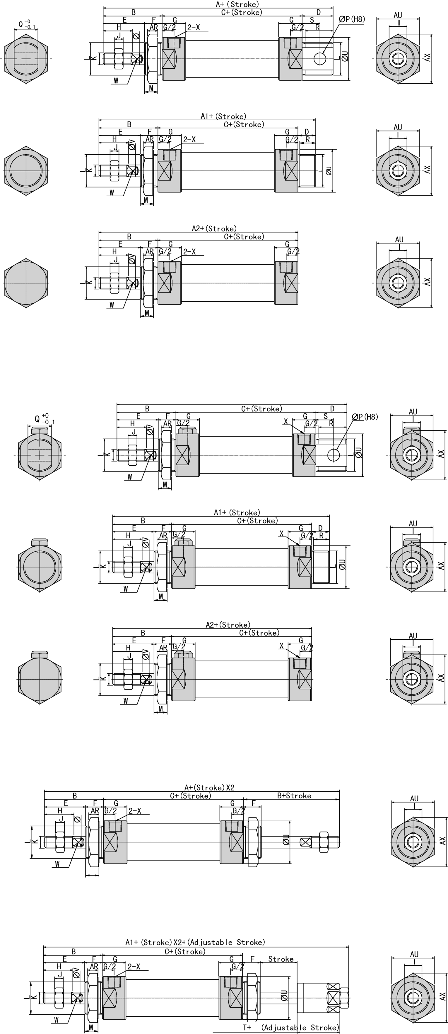
|
|
BORE |
A |
A1 |
A2 |
B |
C |
D |
D1 |
E |
F |
G |
H |
I |
J |
K |
|
16 |
114 |
114 |
98 |
38 |
60 |
15 |
15 |
22 |
16 |
10 |
16 |
10 |
5 |
M6 X 1 |
|
20 |
137 |
128 |
116 |
40 |
76 |
21 |
12 |
28 |
12 |
16 |
20 |
12 |
6 |
M8 X 1.25 |
|
25 |
141 |
134 |
120 |
44 |
76 |
21 |
14 |
30 |
14 |
16 |
22 |
17 |
6 |
M10 X 1.25 |
|
32 |
147 |
134 |
120 |
44 |
76 |
27 |
14 |
30 |
14 |
16 |
22 |
17 |
6 |
M10 X 1.25 |
|
40 |
149 |
136 |
122 |
46 |
76 |
27 |
14 |
32 |
14 |
16.7 |
24 |
17 |
7 |
M12 X 1.25 |
|
BORE |
L |
M |
P |
Q |
R |
R1 |
S |
U |
V |
W |
X |
AR |
AX |
AY |
|
16 |
M16 X 1.5 |
14 |
6 |
12 |
14 |
14 |
9 |
21 |
6 |
5 |
M5 |
6 |
24 |
28 |
|
20 |
M22 X 1.5 |
10 |
8 |
16 |
19 |
12 |
12 |
27 |
8 |
6 |
G1/8 |
7 |
33 |
29 |
|
25 |
M22 X 1.5 |
12 |
8 |
16 |
19 |
14 |
12 |
30 |
10 |
8 |
G1/8 |
7 |
33 |
29 |
|
32 |
M24 X 2.0 |
12 |
10 |
16 |
25 |
14 |
15 |
35 |
12 |
10 |
G1/8 |
8 |
37 |
32 |
|
40 |
M30 X 2.0 |
12 |
12 |
20 |
25 |
14 |
15 |
42 |
16 |
14 |
G1/8 |
9 |
47 |
41 |
|
SÍMBOLO |
A |
|
A1 |
|
A2 |
|
B |
C |
|
D |
D1 |
E |
F |
G |
H |
I |
|
BORE |
0~50 |
51~100 |
0~50 |
51~100 |
0~50 |
51~100 |
|
0~50 |
51~100 |
|
|
|
|
|
|
|
|
20 |
137 |
162 |
128 |
153 |
116 |
141 |
40 |
76 |
101.0 |
21 |
12 |
28 |
12 |
16 |
20 |
12 |
|
25 |
141 |
166 |
134 |
159 |
120 |
145 |
44 |
76 |
101.0 |
21 |
14 |
30 |
14 |
16 |
22 |
17 |
|
32 |
147 |
172 |
134 |
159 |
120 |
145 |
44 |
76 |
101.0 |
27 |
14 |
30 |
14 |
16 |
22 |
17 |
|
40 |
149 |
174 |
136 |
161 |
122 |
147 |
46 |
76 |
101.0 |
27 |
14 |
32 |
14 |
22 |
24 |
17 |
|
SÍMBOLO |
J |
K |
L |
M |
P |
Q |
R |
R1 |
S |
U |
V |
W |
X |
AR |
AX |
AY |
|
BORE |
|
|
|
|
|
|
|
|
|
|
|
|
|
|
|
|
|
20 |
6 |
M8 X 1.25 |
M22 X 1.5 |
10 |
8 |
16 |
19 |
12 |
12 |
27 |
8 |
6 |
G1/8 |
7 |
33 |
29 |
|
25 |
6 |
M10 X 1.25 |
M22 X 1.5 |
12 |
8 |
16 |
19 |
14 |
12 |
30 |
10 |
8 |
G1/8 |
7 |
33 |
29 |
|
32 |
6 |
M10 X 1.25 |
M24 X 2.0 |
12 |
10 |
16 |
25 |
14 |
15 |
35 |
12 |
10 |
G1/8 |
8 |
37 |
32 |
|
40 |
7 |
M12 X 1.25 |
M30 X 2.0 |
12 |
12 |
20 |
25 |
14 |
15 |
41.6 |
16 |
14 |
G1/8 |
9 |
47 |
41 |
|
BORE |
A |
A1 |
B |
C |
E |
F |
G |
H |
I |
J |
K |
|
20 |
156 |
153 |
40 |
70 |
28 |
12 |
16 |
20 |
12 |
6 |
M8 X 1.25 |
|
25 |
164 |
161 |
44 |
70 |
30 |
14 |
16 |
22 |
17 |
6 |
M10 X 1.25 |
|
32 |
164 |
161 |
44 |
70 |
30 |
14 |
16 |
22 |
17 |
6 |
M10 X 1.25 |
|
40 |
168 |
164 |
46 |
92 |
32 |
14 |
22 |
24 |
17 |
7 |
M12 X 1.25 |
|
BORE |
L |
M |
U |
V |
W |
X |
AR |
AX |
AY |
T |
|
20 |
M22 X 1.5 |
10 |
29 |
8 |
6 |
G1/8 |
7 |
33 |
29 |
19 |
|
25 |
M22 X 1.5 |
12 |
34 |
10 |
8 |
G1/8 |
7 |
33 |
29 |
21 |
|
32 |
M24 X 1.5 |
12 |
39.5 |
12 |
10 |
G1/8 |
8 |
37 |
32 |
21 |
|
40 |
M30 X 2.0 |
12 |
49.5 |
16 |
14 |
G1/4 |
9 |
47 |
41 |
21 |
|
|
Hardware De Montaje |
RESTO DEL PIE |
REBORDE DE FRONT/REAR |
SOPORTE de la HORQUILLA con el PERNO |
SOPORTE de la HORQUILLA con el PERNO |
OSCILACIÓN
SOPORTE |
HORQUILLA de ROD con el PERNO |
HORQUILLA de ROD con el PERNO |
|
|
|
MODELO |
LA |
FA/FB |
CA |
CB |
TC |
I |
Y |
|
|
| |
 |
 |
 |
 |
 |
 |
 |
|
|
| |
|
Interruptores de láminas |
Sensor De Posición Del Efecto De Pasillo |
|
|
|
|
|
|
